logo
menu icon
 Tools & Apps

Installing and Splicing Steel Cord Conveyor Belts

Belt Mistracking

The following six chapters clearly demonstrate how to mount and splice steel cord conveyor belts. Using the mouse, simply click the desired chapter.

  • To prepare the splice, the two belt ends are pulled together so they overlap. The length of the overlap is the same as that of the splice. The two belt ends are then aligned 10 m in front of and behind the area of the belt to be worked on. The center lines are marked on the belt ends and then precisely aligned with the help of a guide string. Depending on the press to be used, the splice is either cut square or at an angle. The bevel corresponds to 0.3 x the belt width. After the alignment has been completed, both belt ends must be fixed into place. This is done to prevent them from shifting against each other during subsequent work.

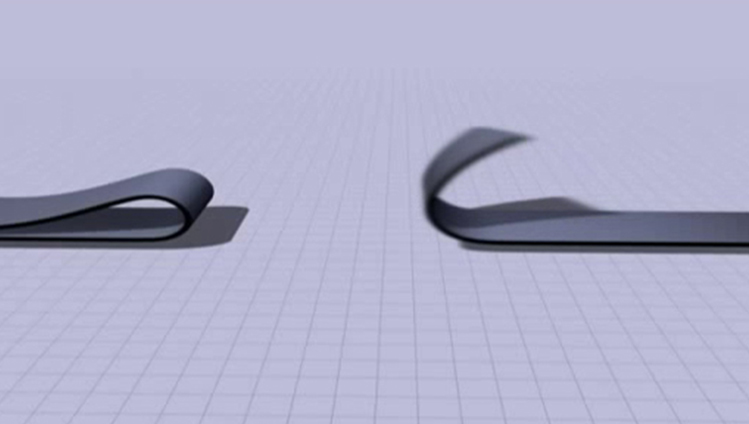
    1. Aligning the Belt Ends

  • The covers are cut at an angle of 60° to the cord position in accordance with the splice geometry. Make sure that the cord is not damaged by the incision. To make separation (stripping) easier, the cover can be divided into strips running parallel with the length of the belt. Starting at a corner of the splice, strip away the cover stock on the joint edge from over the cords. During stripping, the blade must be held inclined slightly toward the belt surface so that a core rubber coating remains on the cord.

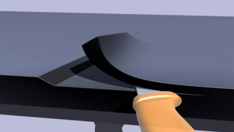
    2. Stripping Away the Cover Stock

  • The cords can be stripped out manually or with the use of a 'strip tool'. If a 'strip tool' is used, step 2 can be skipped. If the cords are stripped manually, the cords are stripped out on six or eight sides. Once the cords have been stripped out, most of the rubber remaining on the cords is removed first with the use of a suitable knife and then by means of rotating steel brushes.

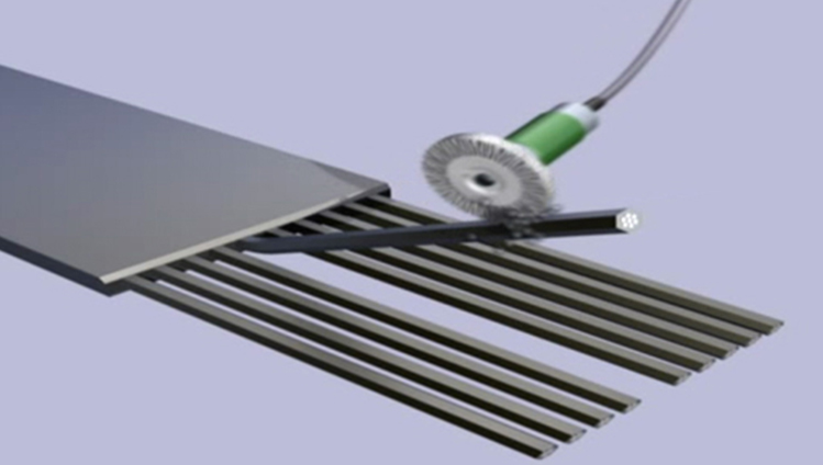
    3. Isolating Individual Cables

  • The bottom cover is cut to size, corresponding to the splice joint lines. After the precise positioning of the bottom cover has been verified, the joint surfaces are fixed into place. This work must be carried out carefully and precisely if the final splice is to be straight, thereby ensuring that the conveyor belt tracks optimally. On the bottom cover, the joint's center line and the reference lines are marked corresponding to the arrangement of the step sequences. On the bottom cover, the central cords of each of the belt ends are cut to the length specified in the splice diagram, and firmly laid or malleted into place on the bottom cover along the center line. The core rubber splicing strips are positioned on their edges to either side of the cords arranged in place. Now cords and core rubber strips are positioned in alternating arrangement as shown in the layout diagram.

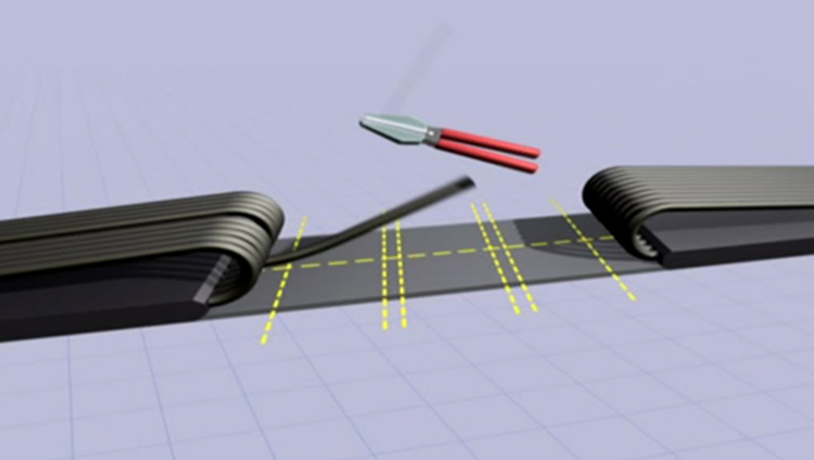
    4. Assembling the Cables

  • The unfilled intermediate spaces in the cord deflection zones and cord joint edges are carefully padded with core rubber strips. Finally, the top cover is cut to size and placed in position. Here, it is important that the transition to the belt is smooth.

    5. Closing the Splice

  • The entire surface of the splice is covered with a pressure blanket. Edge irons are positioned on both edges of the belt. They must be approximately 1 mm thinner than the thickness of the belt. In the same way as for the underside, heating platens are placed on the entire upper surface of the splice. The upper heating platens are then positioned such that they are flush with the edges of the lower platens. The upper beams are now positioned such that they are flush with the lower beams. Tie bolts are affixed to the front sides of the beams and tightened slightly so that they are held securely in place. The pressure, temperature and vulcanizing time are set depending on the belt type. Upon completion of the vulcanization, the pressure is gradually reduced after the temperature has dropped to 80°C. Once the vulcanizing press has been dismantled, the splice must be checked and any expelled rubber removed.

    6. Vulcanizing the Splice